Electrics and Wiring
I have always thought that the 6V system on the XT500 was woefully in adequate. Enough to pass an MOT but hopeless on country lanes without street lighting. So I thought I would finally sort out the XT500 wiring and electrics during this restoration, and install a 12V system. I bought a new 12V kit from Rex’s Speed Shop in the UK, I did this well in advance so had it sitting around the garage for months before it came to using installing it.
I do not enjoy doing electrics, I find it all too confusing, like another language, and have a fundamental lack of understanding of it. I have gained a lot of knowledge from this project and more so from the XT500 forum. I think it is possibly the most talked about topic.
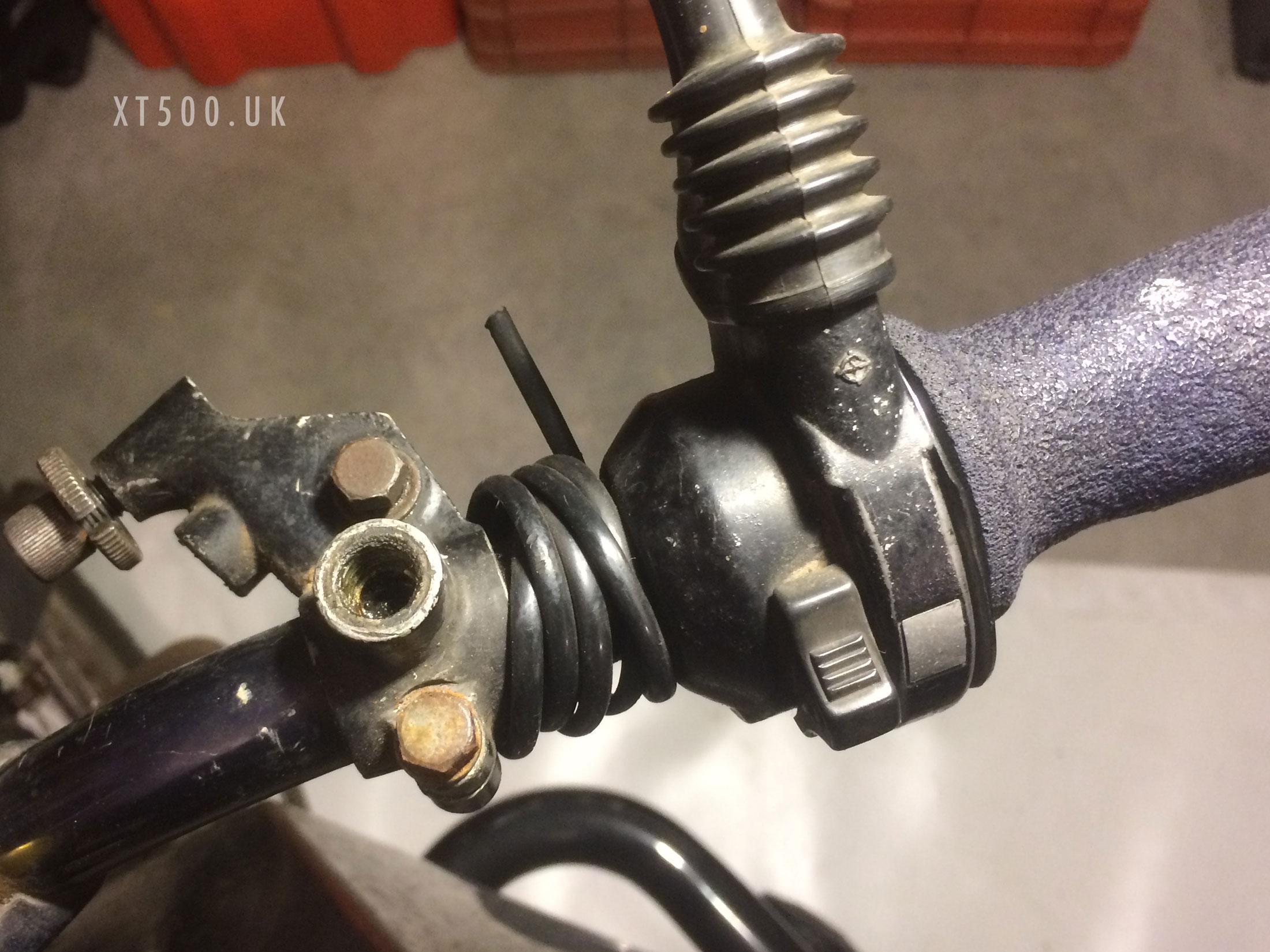
I’ve never had the stop switch connected on my XT500 for as long as I can remember. The key or decomp lever do that job too 😉
I cannot remember why I disconnected it (if I did) but the wire was still attached, just no connector. It’s a black/white wire (in a thicker black sheath) that should be connected directly to the earth (ground) connector at the coil. I have also seen a diagrams that says it should be earth directly to the handlebar. In which case the handlebar would need a good earth connection to the loom somewhere.
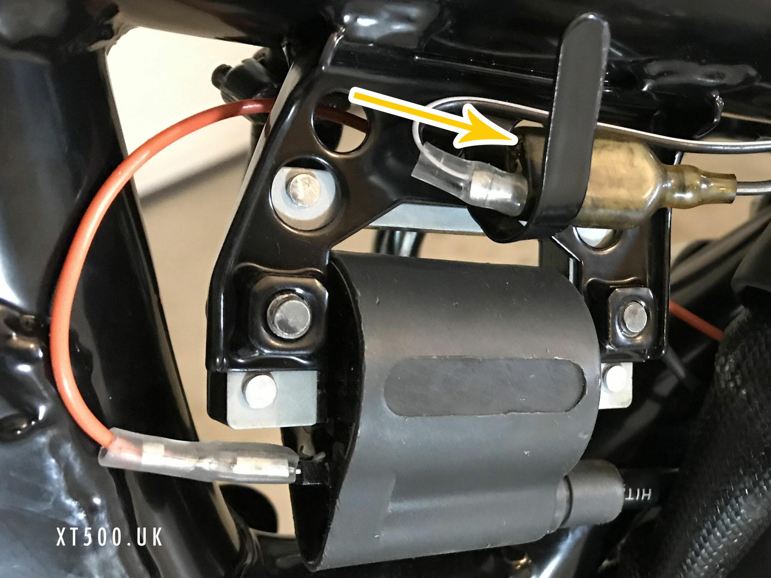
The original loom was installed back on the bike along the correct route and through the correct holes in the rear of the head light bowl. I had labelled all the connectors before dismantling months ago. In this way I could at least get it back to the state it was in knowing that all worked except horn, high beam, neutral lights and brake switches (blown tail light bulbs happened often). I didn’t have indicators preferring to use my arms. One thing to remember – there is a small black earth wire that connects the battery negative terminal to the frame. It connects at the top of the battery box under the seat.
I didn’t know why but many moons ago I had hacked two wires together with solder (badly). Probably due to not having a crimping tool nor the correct male and female ends to fit in the plastic connectors, and not having an understanding of what I was doing. I never discovered why it worked soldering the yellow to the red/yellow.
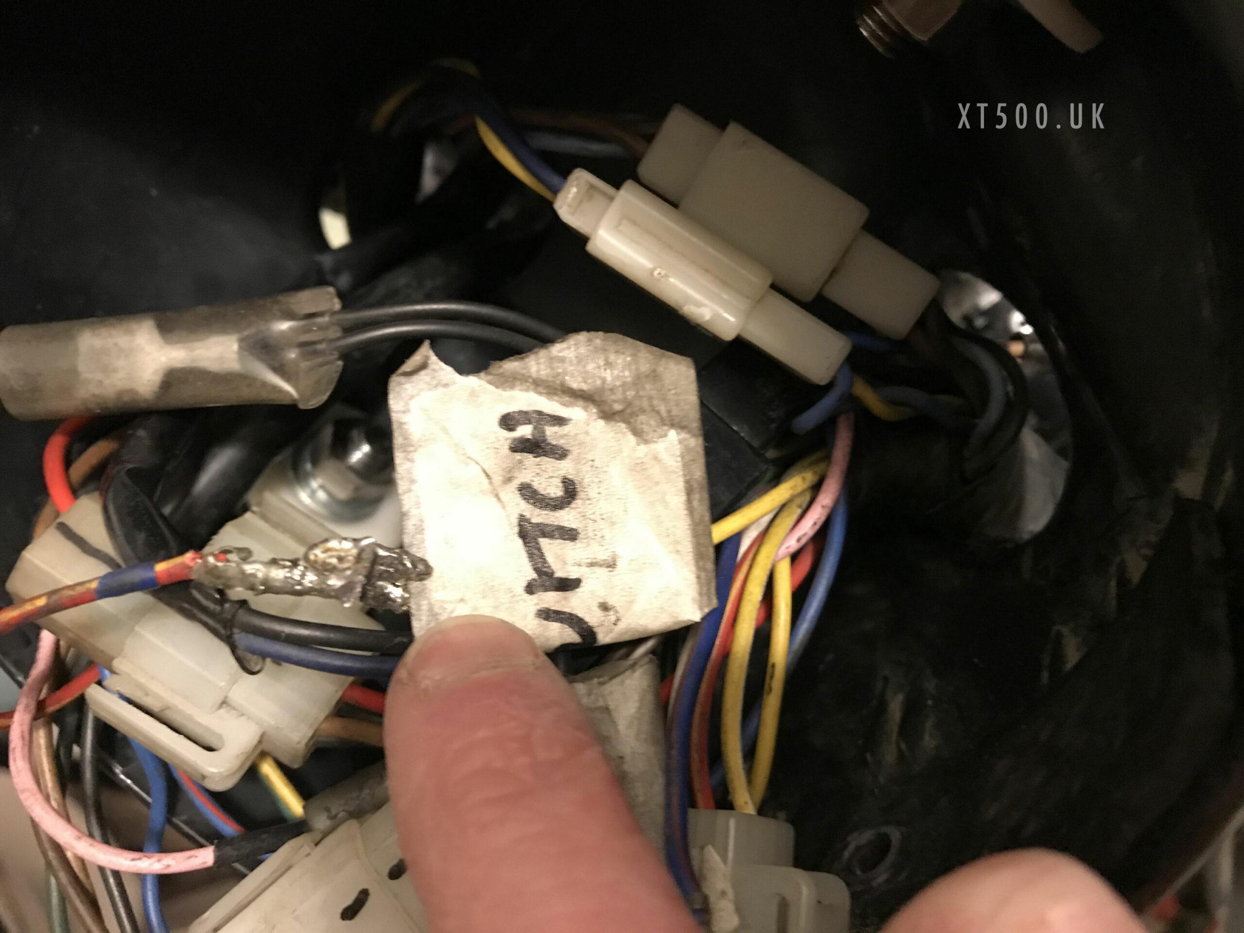
The biggest issue for me to understand and overcome was the fact that the ignition switch had one connector to feed into the headlight bowl, but from wiring diagrams it should have had two. This left a redundant connector block in the headlight bowl, in fact it was there that the soldered red/yellow wire came from.
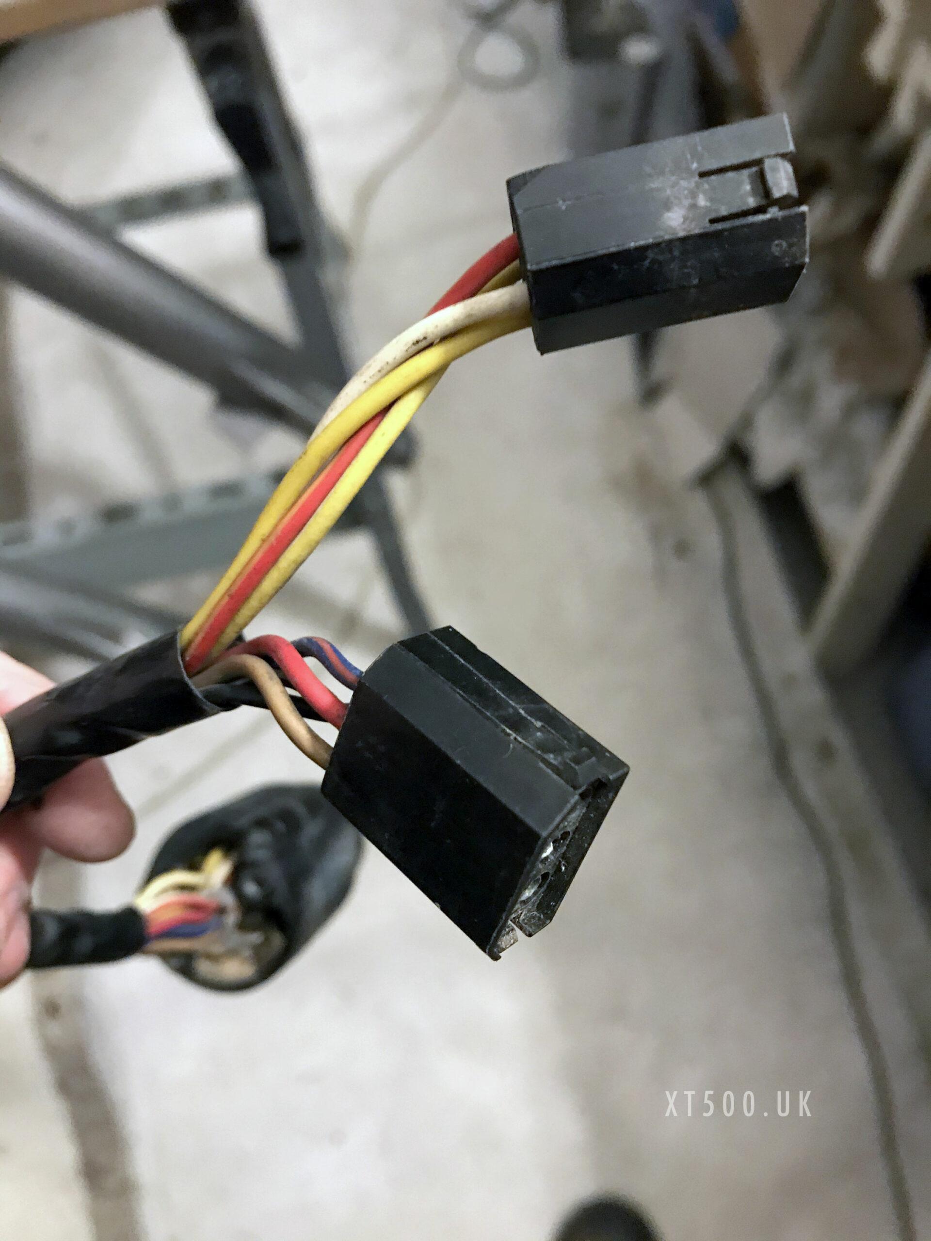
I spent hours over many days of head scratching, getting lots of advice and gazing at many differing wiring diagrams from different models and countries. I even ended up drawing the diagram based on my loom and 12V conversion. In the end I found another diagram that I used, realising that my ignition switch needed to be replaced with a 4 position switch to match the loom on the bike. I did that by using the one from the donor 1U6 bike.
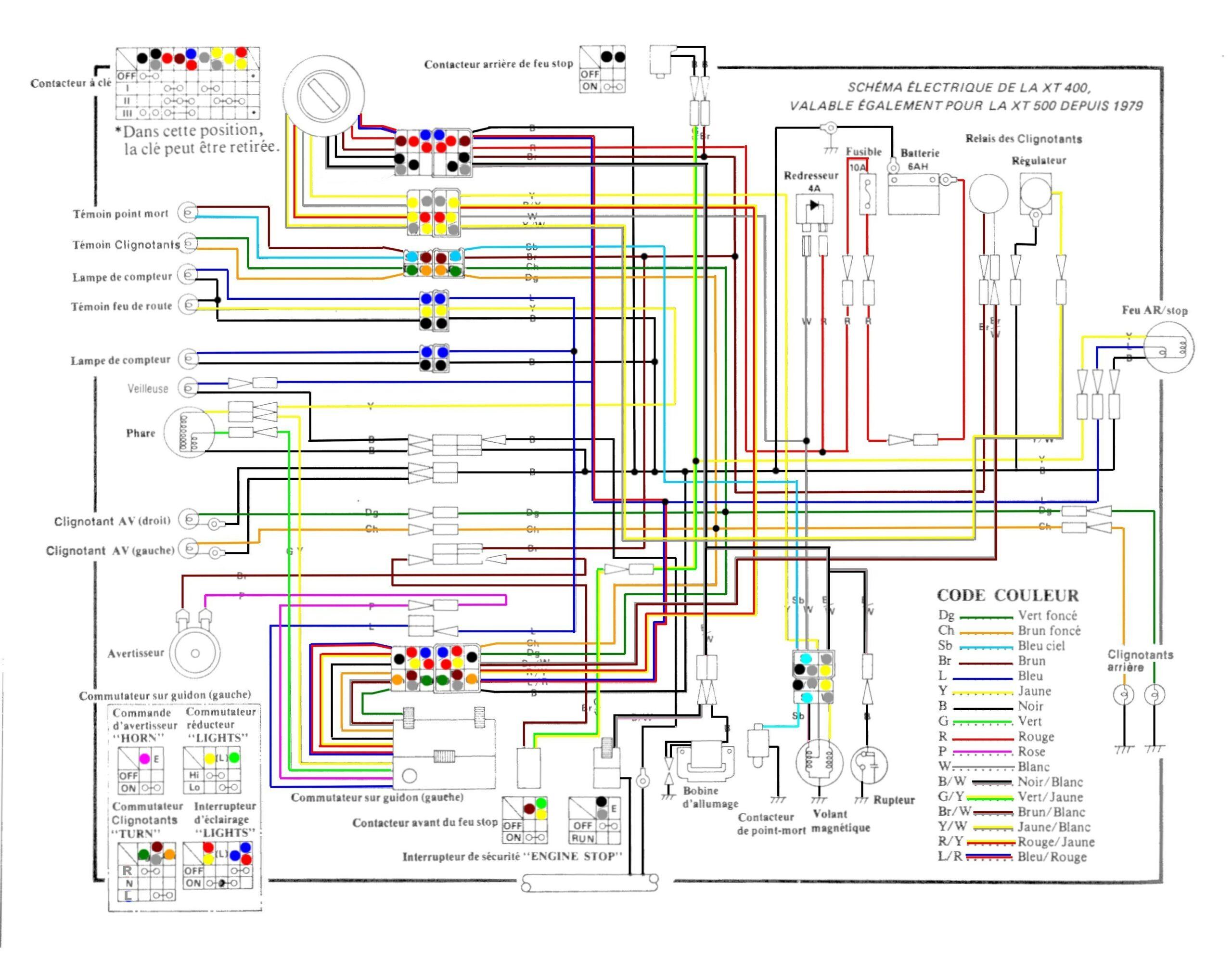
With that installed everything worked except for the indicators (flashers) and of course the headlight but that could only be tested once the engine was running. I couldn’t do that as the wheels had not yet been installed (they weren’t complete yet).
I even had a high beam, neutral light working. Never had that before.
One thing I have learnt doing this is that most wiring issues come from bad connections, particularly the negative grounding. For example it turned out that the rear indicators weren’t working due to the fact that the brackets needed to ground to the frame and the frame had been newly powder coated. By filing away some of the paint inside the mounting bolt hole meant there was now a metal to metal join and therefore grounded (earthed). Similarly the front ones required earth cables since they are handlebar mounted.
XT500 12V Electronic Ignition (Roadster) RMK2-12V
- CNC Billet stator
- electronic ignition unit
- 12 volt lighting coil
- voltage regulator HT coil
- Does away with contact breakers and mechanical advance unit
- Easy starting hot or cold compared to points ignition
- Less maintenance & crisper performance
12V Accessory Pack
- 4 x 21W indicator bulbs
- 1 x stop/tail bulb
- 1x pack of 10 instrument/pilot light bulbs
- 1 x 12 volt electronic indicator relay
- 1 x 12 volt horn
Extras
- MotoBatt MB3U 12V gel battery cannot be shipped abroad so I bought that in Italy
- Spare headlamp and tail light bulbs (couldn’t believe that they wouldn’t still be blowing regularly)


